

IL / RL / PDL
Transmission and polarization
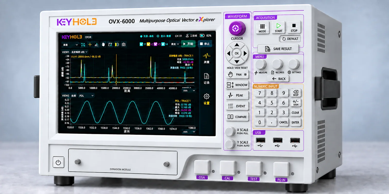
Evaluate insertion loss, return loss and polarization-dependent loss for component characterization and channel comparison.
OPTICAL VECTOR EXPLORER
Measure optical loss, reflection locations, polarization characteristics and optical power spectra on one platform.
Built around a tunable laser source (TSL) and coherent optical measurement, the platform connects swept-wavelength operation, component analysis and multichannel testing. Depending on configuration, OSA functions analyze optical power versus wavelength, spectral peaks and spectral bandwidth for optical communications and silicon photonics R&D.
Supported spectrum types, resolution and available OSA functions are subject to the confirmed configuration.
01 / MEASUREMENT
From end-to-end loss to spatial distributions, build multidimensional measurement results for the same device under test in the same state.
Evaluate insertion loss, return loss and polarization-dependent loss for component characterization and channel comparison.
Use reflection distributions along the optical path to locate anomalies and investigate connectors, coupling interfaces and waveguides.
Combine spectral analysis and wavelength measurement capabilities to provide data for optical power spectrum analysis and wavelength verification.
Use a MEMS optical switch to connect multiple channels for sequential scanning and analysis, reducing manual switching.
TSL / TUNABLE LASER
Wide tuning range, wavelength accuracy and narrow linewidth provide a controlled source for spectral characterization and coherent measurements.
1500–1610 nm tuning range
Adjustable sweep speed: 0–1000 nm/s
Absolute wavelength accuracy
Wavelength repeatability: ±0.05 pm
Laser linewidth
Side-mode suppression ratio: ≥50 dB
24-hour wavelength stability
Output power: ≥10 mW
* The values shown refer to a 1500–1610 nm source configuration covering the C band. Applicable operating modes and test conditions for accuracy, repeatability, linewidth, stability and power must be confirmed for the selected model.
The O band is a separate configuration option; its tuning range and performance specifications require separate confirmation. This does not indicate continuous tuning from the O band to the C band or a common source configuration across all OVX models.
See the scope note above. Confirm scan mode, speed, environmental conditions and delivered specifications during configuration.
Applications are grouped by device under test and test objective. The TSL provides a controlled optical source; detection, polarization and motion control are selected for the task.
Optical communications
For packaged filters, multiplexers and demultiplexers, combine a tunable source with power detection and a reference path to measure insertion loss, passbands and channel isolation for component selection, incoming inspection and production testing.
Silicon photonic integration
For waveguide, microring and interferometer test structures on wafers and bare dies, use optical coupling and detection to record transmission spectra and extract resonance wavelengths, free spectral range and extinction ratio for design verification, process comparison and die screening.
Photonic computing and quantum photonics
For programmable interferometer networks and photonics experiments, provide a wavelength-selectable input and combine external modulation, control and detection for classical optical circuit calibration and parameter sweeps. Coherence, phase noise and wavelength compatibility must be confirmed for the experiment; single-photon generation and quantum-state measurements require additional dedicated systems.
02 / PRODUCT SERIES
Select an OVX configuration based on wavelength band, channel count and analysis requirements.
32-channel O+C-band configuration for multichannel component analysis and automated test workflows.
| Parameter | Trace mini | Standard | Pulse* | Pro* |
|---|---|---|---|---|
| Channels | 1 | 1 (expandable to 16 / 32) | 32 | 64 |
| Wavelength band | C-band | C-band | O+C bands | O+C bands |
| RL dynamic range | ≥70 dB | ≥85 dB | ≥85 dB | ≥110 dB(EDFA) |
| Spatial resolution | ≤100 μm | ≤12 μm | ≤8 μm(C-band) | ≤8 μm(C-band) |
| OSA resolution | — | 0.08 nm | 0.08 nm | 0.048 nm |
| Wavelength meter accuracy | — | ±0.3 pm | ±0.2 pm | ±0.2 pm |
* Pulse and Pro are unreleased series. Listed specifications are preliminary; final configurations, features and availability are subject to formally released technical documentation.
These are proposed series specifications. Capabilities and test conditions are subject to the configuration and technical specification agreed by both parties. Product images illustrate the platform appearance, not the complete hardware configuration of each model.
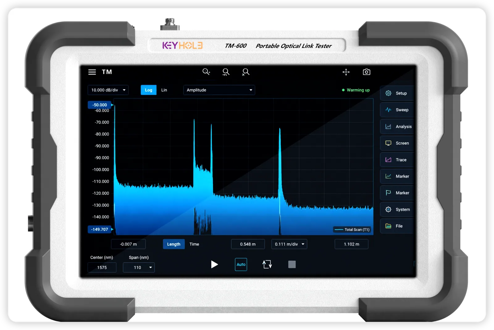
PORTABLE / TRACE MINI
KH-OVX-Trace mini · Portable optical link tester
A compact, single-channel C-band instrument configuration for optical link interferometric measurements and anomaly localization.
Parameters come from the product series plan; test conditions are subject to the agreed technical specification. TM-600 is the appearance nameplate shown in the image.
03 / APPLICATIONS
Organize optical testing around four test insertions for CPO and silicon photonic devices.
Evaluate waveguide IL, RL and PDL before bonding to help identify optical anomalies.
Focus: optical quality screeningUse reflection information from coherent optical measurements to investigate post-bond optical path integrity and support coupling-alignment verification.
Focus: connectivity and alignmentCombine loss, polarization, wavelength and spectral analysis for optical engines and multichannel components.
Focus: channel-to-channel consistencyVerify optical parameters in finished modules and retain records for outgoing quality assessment and reliability analysis.
Focus: results and traceability04 / PLATFORM
Coherent optical swept measurements connect to MEMS multichannel scanning, followed by software analysis, to form an integrated test workflow.
DESIGNED FOR DAILY OPERATION
Channel expansion, optical interfaces and automation data integration can be discussed per project. Platform plans describe MEMS expansion toward 1–128 channels; actual channel counts, cycle time and protocols require DUT-specific confirmation.
SOFTWARE
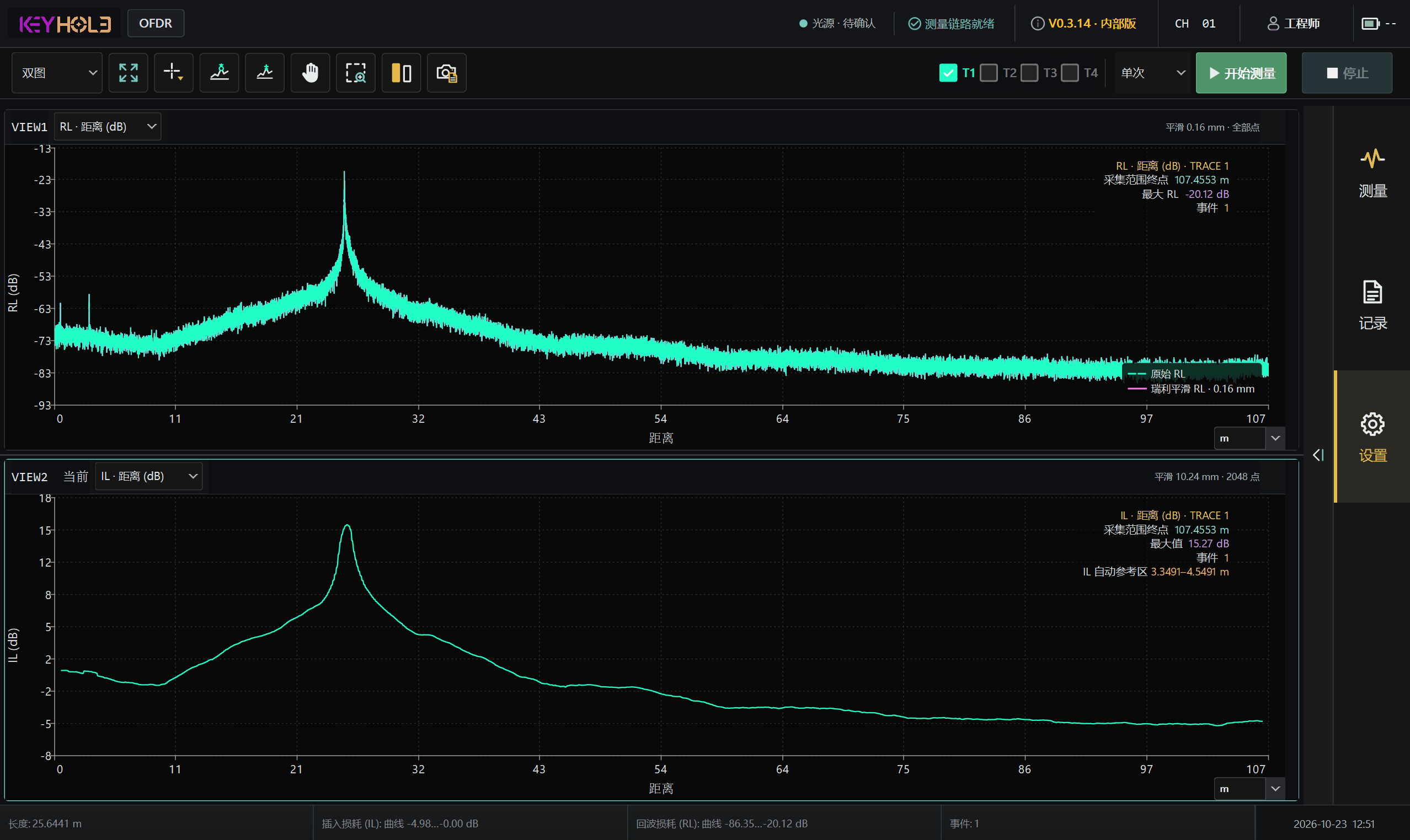
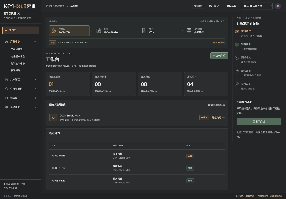
Efficient, simple, modular, platform-based and standardized—reducing the learning curve for seamless transitions and productive measurements.
Reduce operating effort with intuitive interfaces and connect test workflows through standardized control. Consistent configuration, measurement, analysis and records support modular expansion and workflow reuse. Interface availability and compatibility depend on the product version.
MEASURE & ANALYZE
Measurement and analysis workspace
DISTRIBUTE & MANAGE
Application and version management platform
SERVICE & TRACE
Technical service and issue-tracking platform
Interfaces illustrate product concepts. Available functions, supported instruments and licensing depend on the delivered version.
05 / SELECTION GUIDE
First confirm the DUT wavelength bands and ports. Standard is a starting point for single-channel C-band tasks; Pulse corresponds to the proposed 32-channel O+C-band configuration; Pro addresses 64 channels or higher RL dynamic range, subject to EDFA configuration and test-condition confirmation.
The documented architecture uses MEMS 1:N sequential scanning, switching between channels in turn. Actual cycle time depends on scan settings, channel count and analysis tasks, and must be verified with representative samples.
Electro-optical testing and automation integration can be discussed for specific projects. Please provide the system architecture, data formats and protocols; supported functionality is defined in the project scope.
Provide the DUT type, key parameters, wavelength bands and channel count so our technical team can assess the configuration, documentation and sample-verification arrangements.