

Wavelength-dependent transmission characteristics
Compare resonance positions, passbands and loss to evaluate design responses and sample differences.
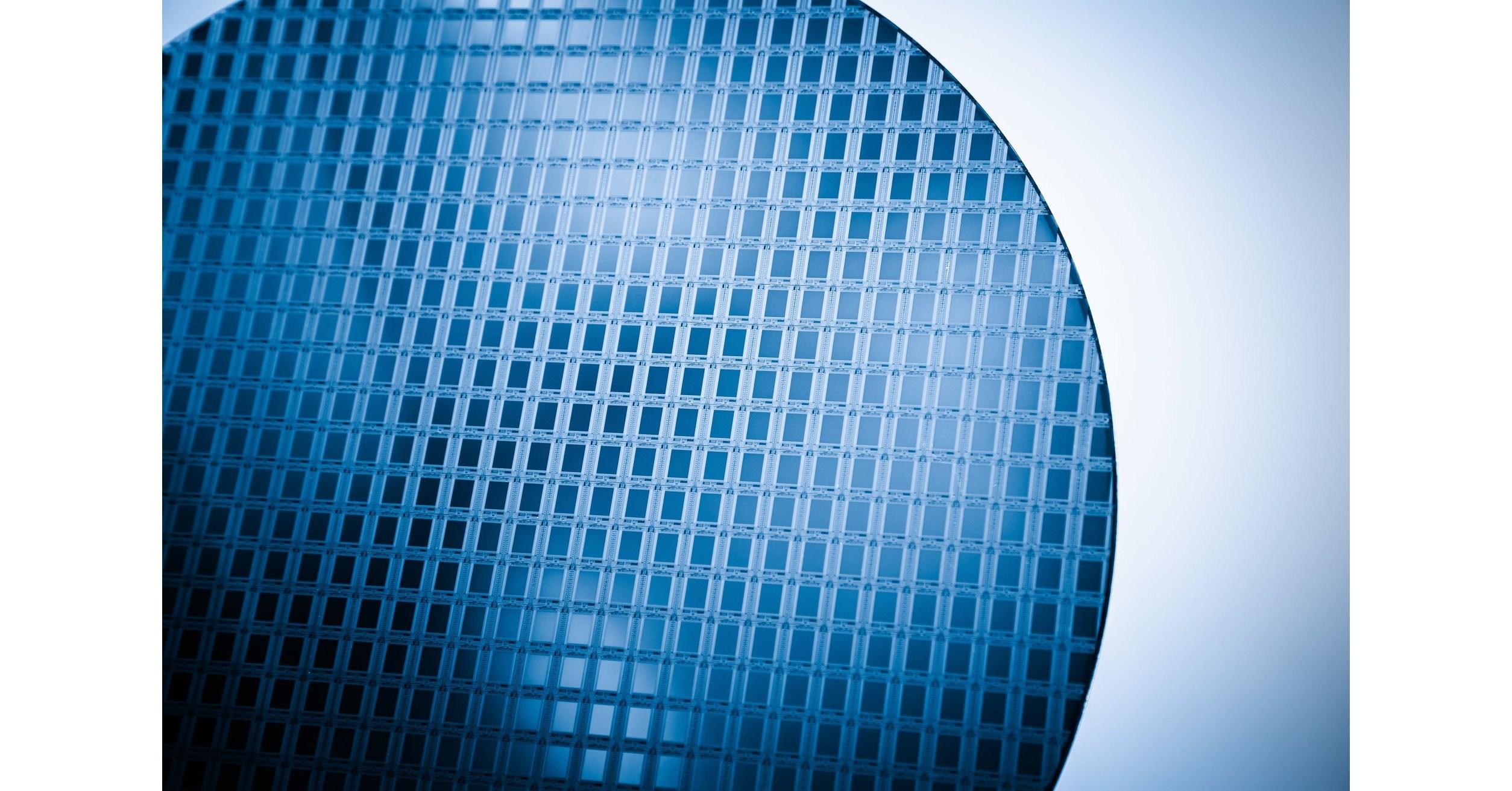
WAFER AND CHIP TEST / Silicon photonics
Understand device performance before packaging. Relate spectral anomalies to spatial information to support design and process development.
01 / WHAT TO MEASURE
Waveguides, microrings, MZIs, splitters and coupling structures in PIC wafers and bare dies. Access depends on probes, coupling and test-station conditions.
Define the DUT, optical access and reference conditions before discussing instruments and analysis capabilities.
02 / ENGINEERING VALUE
Compare resonance positions, passbands and loss to evaluate design responses and sample differences.
When end-to-end results are abnormal, help identify discontinuities along the optical path and narrow the investigation.
Record coupling, polarization and references to avoid attributing condition changes directly to process defects.
03 / MEASUREMENT APPROACH
Define the structure, optical access and reference plane; verify coupling and reference stability first.
Use OVX with its built-in TSL for applicable spectral and coherent optical measurements, analyzing port results alongside structural information.
Add polarization controllers, optical switches and external probe stations as needed; save records by device, position and conditions.
Scope and LimitationsSuitability for wafer optical measurements does not mean a complete automated wafer-test system has been delivered. Wafer mapping, automatic alignment and production cycle time require project-specific validation.
04 / MEASUREMENT EVIDENCE
Connect readings with records so results can be understood, compared and reviewed.
05 / CONFIGURATION
Combine products around the task, not simply the instrument count.
Built-in TSL; choose a configuration based on structure dimensions, method and verified performance.
Multiport access and sequential channel scanning—not simultaneous multiport acquisition.
Combine tools according to polarization objectives, calibration methods and device requirements.
Discuss position identifiers, data association and interfaces. Probe coupling, motion control and hardware interlocks require separate confirmation.
* Pulse and Pro are unreleased series. Listed specifications are preliminary; final configurations, features and availability are subject to formally released technical documentation.
OVX has a built-in TSL; standalone TSLs are configured separately for appropriate user-built optical paths. OVX-TLS, OVX-SW, OVX-PC, OVX-PA, OVX-PDL and OVX-OSA are provisional product-family identifiers, not current delivery commitments. Actual functions, interfaces and performance depend on the confirmed model, method, conditions and version.
06 / DISCUSS YOUR REQUIREMENTS
Provide wafer/die format, coupling method, structure dimensions, bands, port count and probe-station interfaces.
With this information, use the shared contact entry below to discuss your task with an engineer.