

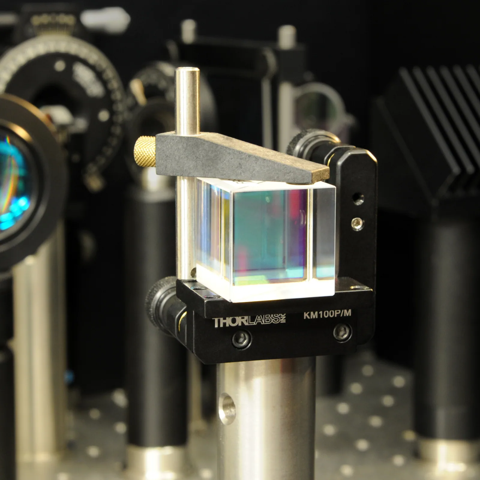
After a spectral test, an engineer disconnects and reconnects the fiber, and the trace changes. Neither source settings nor the device changed. The device may not be damaged: polarization at its input may have changed.
This is especially difficult when comparing small sample differences. If access-condition variation is comparable to the device difference, more repetitions do not automatically prevent misinterpretation. First establish the input conditions represented by the result.
Why Polarization Changes Transmission
Light is an electromagnetic wave; polarization describes how its electric-field vector evolves over time. For a fixed propagation direction, two orthogonal transverse components, their amplitudes and relative phase define the state. Different device responses to these components can make output power depend on input polarization.
Polarization-dependent loss (PDL) describes this transmission difference. With wavelength, input power and other conditions fixed, the maximum and minimum power transmittances give PDL = 10 log₁₀(Tmax / Tmin), in dB. The extrema refer to all possible input polarization states, not two arbitrarily chosen readings.Thorlabs coupler specification reference
PDL is not the insertion loss from one measurement. It describes the transmission range caused by input polarization changes; a single IL reading applies to specified references and inputs. A low-loss operating point does not establish polarization insensitivity.
Why Identical-Looking Fiber Placement Is Not Enough
Stress and bending in ordinary single-mode fiber influence polarization evolution. Visually identical connector placement does not establish the same polarization at the device.Newport fiber polarization tutorial
In silicon photonics, distinguish the input fiber state from the on-chip mode actually excited. Polarization-selective coupling can change both access efficiency and measured response. Calling every change chip loss obscures the coupling contribution.
Polarization helps define the measurand, rather than being an afterthought. Measuring performance in a specified mode and evaluating response across input states are different objectives requiring different interpretations.
Maximum Power Does Not Complete a PDL Measurement
Optimizing input for high transmission can serve mode selection or coupling optimization, but only establishes that operating point. It neither finds minimum transmission automatically nor proves full polarization coverage.
Changing polarization a few times and taking extrema reports only the sampled range. Without validated coverage and methodology, it cannot establish the device's true worst case.
Commercial approaches also reconstruct polarization-dependent responses using matrix methods, as described in Keysight's materials. Manual extrema search is not the only approach; each method has its own model, reference and applicability conditions.Keysight polarization and dispersion reference
Include Polarization Conditions in Sample Comparisons
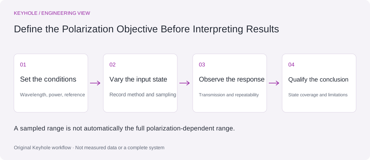
For R&D comparison, fix the band, reference plane and access method, then state whether polarization is maintained, optimized or changed through a defined sequence. Cross-station reports should retain the method and available state records, not just final loss.
If traces change after reconnection, leave the device undisturbed where possible, check references and input power, then vary polarization under control. A systematic dependence warrants further characterization; concurrent access drift prevents attributing the entire difference to the device.
The purpose is not complex control in every test but explicit conditions that influence decisions. Device differences become easier to explain when input variation is controlled or documented.
How Polarization Sensitivity Affects Engineering Choices
A system operating in a specified state or mode may need that state established and maintained. An uncontrolled-input application needs its response range assessed against its budget. A PDL value alone cannot determine selection without application context.
Distinguish polarization control, state-of-polarization analysis and PDL analysis when selecting instruments. A controller changes inputs, an analyzer observes states, and PDL analysis requires a complete method. Having one does not complete the others; configure around the DUT and decision.